
What is Ignition system in car? How Ignition system work in a car
Understanding the Components of Ignition Systems: A Detailed Breakdown of Spark Plugs, Ignition Coils, and Their Roles in Engine Performance.
What is ignition system: The method by which in the petrol engine heat energy is generated in the engine by causing a spark between the compressed air and fuel mixture in the combustion chamber is called “Ignition Method”.
Functions of ignition system: The function of the ignition system is to convert the low voltage from the storage battery into a high voltage used in the ignition circuit. The 6 or 12 volts from the storage battery are converted to a voltage of 21,000 to 25,000 volts by the ignition coil, and the spark occurs when the circuit is completed by the opening and closing of the CB point.
Sparks occur at a specific time. Ignition timing determines this time. This spark occurs at the end of the compression stroke, 15 to 19° before the piston reaches TDC (Top Dead Center).
This ignition system starts sparking 10° before the end of the compression stroke and continues until 10° after the piston passes TDC. In this case, the ignition system follows the ignition timing.
In the combustion chamber of a petrol engine, if sparking occurs at the right time and properly, the mixture of compressed air and petrol combusts smoothly, generating moderate heat energy in the engine. After this thermal energy is converted into mechanical energy, the ignition system helps to drive the engine.
4 Types of Ignition System
The ignition system of a petrol engine is basically divided into two categories:
- Battery Ignition System
- Magneto Ignition System
Battery ignition systems are further classified into two types:
(a) Conventional battery ignition system
(b) Transistorized battery ignition system.
Magneto ignition systems are also divided into two types:
(a) Moving magnet type ignition system
(b) Stationary magnet type ignition system.
Application: Among these, the conventional battery ignition system is commonly used in engines of petrol jeeps and cars, while the magneto ignition or transistorized battery ignition system is used in the engines of motorcycles, scooters, and taxi.
Parts of ignition system:
- Storage battery,
- Ammeter,
- Ignition switch
- Ignition coil,
- Ignition Distributor
- Spark plug (Spark plug).
Electronic ignition system

The electronic ignition system is used as the ignition system in modern automobiles. In this system, components like the storage battery, ignition switch, side resistor, magnetic pulse distributor, ignition pulse amplifier, reluctor (or timer core), and ignition coil work together. It uses transistors, capacitors, and diode amplifiers to control the power. No CB point (contact breaker point) is used in the electronic ignition system. Instead, a magnetic pick-up coil is used in the distributor, along with amplifiers and transistors.
The rotor used in this system is called a Reluctor or timer core. It replaces the breaker arm. The engine has as many reluctors or timer cores as there are cylinders, and each is placed adjacent to a permanent magnet and a pick-up coil. The rotation of the distributor shaft generates force in the magnet’s field, which operates the low-current control unit. The electronic components in the control unit, such as diodes, capacitors, and amplifiers, help in converting, amplifying, and regulating the electricity. Power from the pick-up coil reaches the control unit, which manages the flow of power to the system. As a result, the magnetic field in the ignition coil is interrupted, and high voltage is generated in the secondary coil.
leo.
Battery CDI (Capacitor Discharge Ignition)
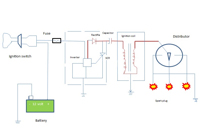
In the battery CDI (Capacitor Discharge Ignition) method, the 6V or 12V from the battery is converted to 400 volts AC with the help of an inverter, and then to 400 volts DC using a rectifier. A thyristor or SCR (Silicon-Controlled Rectifier) is used as an electronic switch. When the electronic switch is off, the capacitor is charged to 400V. Once the electronic switch is turned on, the capacitor discharges through the primary winding of the ignition coil, producing 40,000V in the secondary winding and causing a spark at the spark plug of the connected cylinder.
The electronic switch “Thyristor” is a four-layer semiconductor with anode, cathode, and gate terminals. Conduction begins as soon as a control signal current is applied to the gate terminal, allowing current to flow from the anode to the cathode. As a result, current passes through the primary winding of the ignition coil, generating an electric flux in the primary winding. When the switch is turned off, the magnetic field collapses, producing up to 400V in the primary circuit, which charges the capacitor.
The electronic control module (ECM) controls ignition timing by receiving signals from the Hall-effect crankshaft sensor. The manifold absolute pressure (MAP) sensor signals engine load to the ECM, and the knock sensor notifies the ECM in the event of knock or detonation. In response, the ECM adjusts and reduces spark advance.
Engine ignition timing

At the end of the compression stroke in a petrol engine, the ignition of the charge, consisting of the compressed air and fuel mixture, at the right time by sparking the spark plug is called ignition timing.
In petrol engines, the ignition system parts are operated by the distributor gear, which rotates in synchronization with the camshaft gear, and the ignition timing is controlled by the ignition system. The valve operates the camshaft through the timing control gear, so valve timing is closely related to the performance of the ignition timing. Correct valve timing ensures that the charge enters the engine’s combustion chamber at the right moment, while a proper ignition system ensures that the charge is combusted at the correct time, efficiently providing power to the engine. When the engine is running, the rotor rotates adjacent to the distributor shaft and moves in a clockwise direction, making contact with the segment or coupling point at the precise time. This contact point is located under the distributor cover, and the number of contact points corresponds to the number of cylinders. The rotor transmits 21,000 to 25,000 volts of electricity to the spark plug, creating a spark.
The cam is attached to the shaft below the rotor. At the center of the distributor cap is the high-voltage line connection, and the rotor receives this current and sends it to the different spark plugs according to the ignition timing and firing order. This high-voltage current is generated in the ignition coil and controlled by the CB point, transferring from the secondary coil to the center of the rotor with carbon brushes. The current then travels through the conductor material to the rotor, and each time, from the rotor end to the brass junction on the distributor cap. A spark occurs when the high-voltage electrical energy passes through the small gap in the spark plug. A spark advance mechanism in the distributor adjusts the ignition timing to either advance or delay as required. Typically, combustion occurs at the end of the compression stroke. Sparking at the spark plug begins around 29° before the piston rises to TDC and continues until about 10° after it reaches TDC. Therefore, the ignition timing ensures the spark is produced at the correct moment.
Common Faults of the Ignition System
Ignition system faults can be divided into three categories:
(a) Power dissipation in the primary circuit,
(b) Power dissipation in the secondary circuit, and
(c) Timing errors.
The possible causes for such faults are as follows:
Possible Causes of Power Dissipation in the Primary Circuit:
- Faulty leads or loose connections causing resistance in the primary circuit; CB points may be burnt, or the primary winding of the ignition coil may be open.
- Incorrectly set CB points.
- Discharged battery or faulty alternator.
- Defective condenser (e.g., low insulation resistance or high series resistance).
- Primary circuit grounded at the coil, wiring, or distributor.
Possible Causes of Power Dissipation in the Secondary Circuit:
- Fouled or broken spark plugs or incorrect spark plug gap.
- High voltage leaks due to faulty high-tension wiring.
- Discharged battery and alternator faulty.
- High voltage leaks through the coil head, distributor cap, or rotor.
- The connection in the high voltage circuit is faulty.
- The ignition coil is faulty.
Faults in Ignition Timing:
- Timing is not set correctly.
- The distributor bearing or shaft is corroded, or the shaft is bent.
- Vacuum advance is defective.
- Centrifugal advance is defective.
- Pre-ignition due to the use of an incorrect heat range plug.
Easy Ways to Fault Finding in the Ignition System without Using Instruments

A primary or secondary fault can be detected without using any instruments or by using only a spark tester in the following ways:
- Remove the high tension lead from the distributor cap.
- Hold the high tension lead 6 mm (¼ inch) away from the engine block using insulated pliers.
- Crank the engine with the ignition switch on. If a strong spark is obtained, the fault is likely in the secondary circuit (distributor to spark plug). If there is no spark or a weak spark, the fault is likely in the primary circuit or in the coil tension lead.
- Crank the engine by disconnecting each spark plug cable and holding it 6 mm away from the engine head using insulated pliers. If there is no spark from any spark plug cable, check that cable’s connection.
- Each spark plug cable can be tested using a spark tester. To test, ground the spark tester and crank the engine, connecting each spark plug cable to the spark tester alternately.